Peter Nicholson,NACE Corrosion 2008 Conference & Expo , Paper No. 08123
Abstract
Traditionally, close interval potential surveys (CIPS) and direct current voltage gradient surveys (DCVG) have been undertaken separately and the corrosion engineer has been saddled with the task of trying to correlate the results of these surveys, to assess the level of cathodic protection on the pipeline and the effect of coating holidays on the effectiveness of the cathodic protection system. This paper outlines a method of undertaking both surveys simultaneously and the benefit to the corrosion engineer of having accurate and correlated surveys. The paper also deals with surveying pipelines affected by stray currents.
Introduction
It is reported in the literature that 30 % of all pipeline failures in Europe in a 30 year period from 1971 to 2001 were due to corrosion (1). “Corrosion Cost and Preventative Strategies in the United States”, published by the US Department of Transportation, Federal Highway Administration in 2002 (2) states in Table 5, page E24 that corrosion accounts for 24.3% of all hazardous liquid pipeline accidents and 25.4% of all natural gas pipeline accidents. It is estimated that in the United States the cost of corrosion and maintenance of pipelines is approximately $7 billion per year. With the proper application of cathodic protection that meets the NACE International Standard Practice SP0169-2007 (4), the accident rate for underground/underwater pipelines can be significantly reduced, thus reducing the cost of corrosion and environmental damage.
Combined CIPS and DCVG Surveys
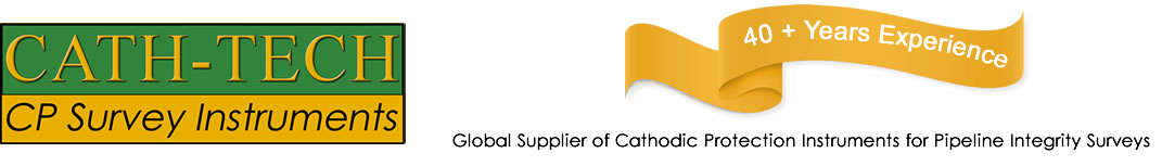
Figure 1 shows a close interval potential survey being undertaken around a pool of spilt crude oil. Had the pipeline operators been vigilant in applying the principles of RP0502-2002 (3) and SP0207-2007 (5), they would have realized that the pipeline was corroding and could have taken action to improve the level of cathodic protection and thus prevented the leak.
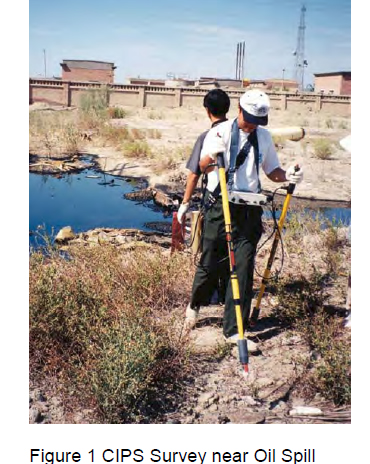
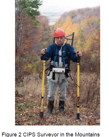
A significant amount of underground or underwater pipelines in the world do not lend themselves to In Line Inspection ILI (Smart Pig) due to their size, geometry or other factors. NACE Recommended Practice RP0502-2002 (3) requires that a close interval survey (Figure 2) be conducted on all underground/underwater pipelines. On pipelines where internal inspection cannot be used, an above ground coating integrity survey should also be performed. There are several methods of undertaking an above ground coating integrity survey. The most popular method is a direct current voltage gradient survey (DCVG), Figure 3. NACE International Standard Practice SP0207-2007 (5) specifies the method of undertaking close interval and DCVG surveys.
Traditionally, these surveys have been undertaken as separate surveys utilizing different instruments. The close interval potential survey has traditionally been done using a data logger and reference electrodes carried over the route of the pipeline recording the pipe-to-soil potentials at regular intervals, usually at less than 3 meter spacing.
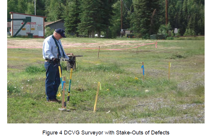
The direct current voltage gradient surveys have traditionally been undertaken with an analogue instrument without a connection to the pipeline whereby the operator stakes out the location of coating defects (Figure 4) and estimates the size or severity of the defect by comparing the voltage gradient associated with the defect to the average potential shift of the pipeline as measured at the closest test stations. Spatial disparity errors occur when the results of two distinctly different surveys are merged or combined, presenting a problem for the corrosion engineer in interpreting the results.
A superior method of measuring the level of cathodic protection and recording the location and severity of coating defects is to undertake a combined CIPS and DCVG survey, using one tool, electronically measuring and recording not only the pipe-to-soil potential and the voltage gradient, but the chainage and GPS coordinates, time and date of each reading, thus eliminating any possibility of transcription errors from hand written notes.
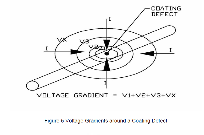
There is a lot of misunderstanding about DCVG surveys, although the principle is quite simple and has been used for many years in various forms. On a coated pipeline that is cathodically protected, current flows from the anode of the cathodic protection system to holidays or defects in the coating. This current flow to the defects can be measured as a voltage between two electrodes on the surface of the ground. The voltage developed between two points on the surface of the ground obeys Ohms law, V = IR where V is the voltage gradient and I is the current flow to the coating defect or holiday and R is the resistance of the soil between the two electrodes (Figure 5). When two electrodes are placed on the surface of the soil, a voltage can develop between the electrodes due to soil chemistry, moisture content, contact resistance, etc. In order to easily sort out the difference between voltages generated by electrode contact with the earth and voltages due to current flow to a coating holiday or defect, the DCVG surveyor pulses the rectifier output by installing a current interrupter that cyclically interrupts the rectifier. Since the DCVG surveyor is limited on how far apart he can place the electrodes on the soil and since the voltage in the soil to a small holiday may only be a few
millivolts, the DCVG surveyor often increases the output of the rectifier to increase the voltage gradient in the soil to make it easier to recognize the current flow to the defect (Figure 6).
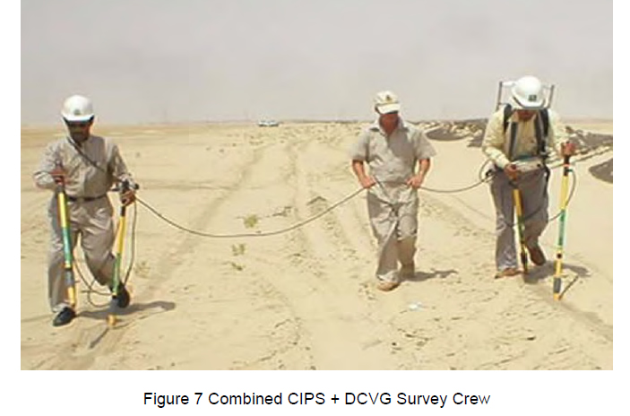
New technology provides a better way of doing a DCVG survey that allows the pipe-to-soil potential to be recorded simultaneously with the DCVG value. Modern electronic instruments are capable of recording several different voltages every second as well as distance, GPS coordinates and time. By utilizing two surveyors (Figure 7), the maximum voltage associated with a defect can be measured and recorded along with its location. More important is the ability to also measure simultaneously the pipe-to-soil potential and voltage gradient with the rectifier on and off. These readings can be measured, displayed and recorded every second along with the chainage (distance), the GPS coordinates, the time and date of each reading and the precision of the 3 dimensional GPS image as the PDOP value.
When undertaking a combined CIPS and DCVG survey, the surveyor must walk on top of the pipeline. Under certain conditions the second or gradient surveyor can walk beside the surveyor about 5 to 7 meters away from the pipeline (Figure 7).
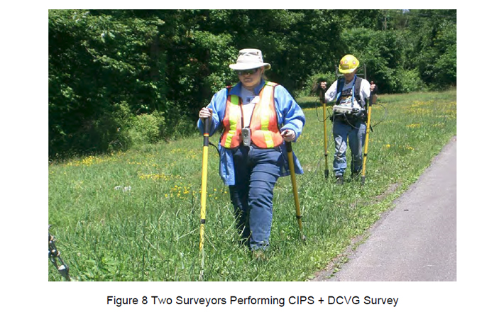
In most instances the second surveyor cannot walk adjacent to the surveyor but must walk ahead of or behind the surveyor (Figure 8), to reduce the incidence of the umbilical cable
getting caught on sticks and brush. When the gradient surveyor walks either ahead of or behind the surveyor, a distinct pattern representing the coating holiday or defect is produced in the form of a sine wave – see Figure 11.
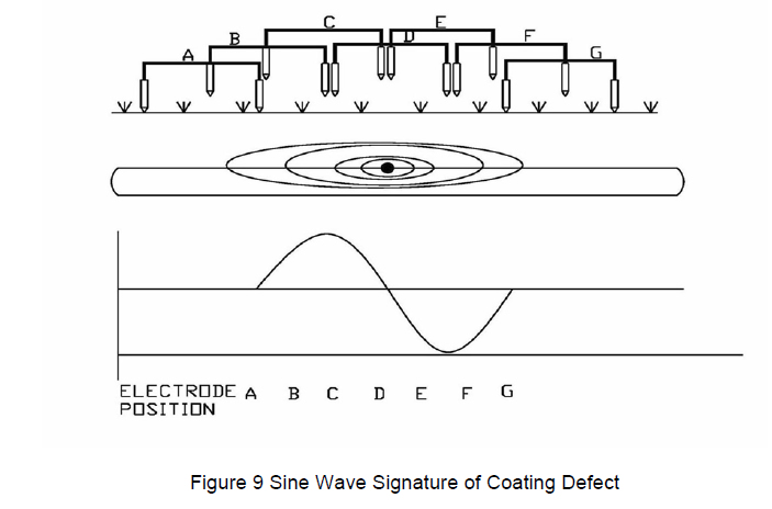
The sine wave is the result of the electrodes measuring the voltage gradient while entering and leaving the voltage gradient field around a coating holiday or defect. As the surveyor approaches a coating defect, the voltage gradient electrode becomes more positive than the trailing surveyors gradient electrode. As the surveyors move along the pipeline, the lead surveyor’s gradient electrode becomes more and more positive in relation to the trailing surveyor’s electrode until the epicenter of the defect is reached. At that location, the maximum voltage gradient is recorded between the lead surveyor’s electrode and the trailing surveyor’s electrode. As the defect epicenter is passed, the voltage gradient measured between the lead surveyor’s and the trailing surveyor’s electrodes decreases. As the trailing surveyor approaches the defect, the voltage is reversed in that the trailing surveyor’s electrode becomes more positive than the lead surveyor’s until the coating defect epicenter is reached. The voltage gradient decreases as the trailing surveyor moves away from the coating defect epicenter – see Figure 9.
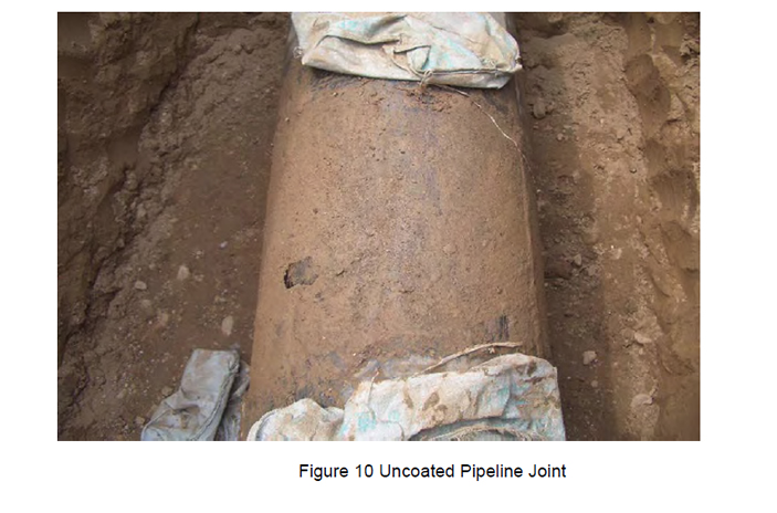
The dual surveyor mode in most instances does not require an increase in rectifier output, as the maximum voltage associated with a defect is measured automatically due to the increased spacing between the two reference electrodes. There are several advantages to the combined CIPS and DCVG survey. Both sets of data are gathered at exactly the same time, in exactly the same place under the same field conditions. The rectifier on and off pipe-to-soil potential is correlated with the DC voltage gradient thus eliminating spatial errors. The corrosion engineer can make a valid judgment on the effect of coating defects or holidays on the pipe-to-soil potential, thus eliminating any guesswork on whether the defect should be excavated and repaired. Figure 10 shows an uncoated pipe joint located by a combined CIPS and DCVG survey.
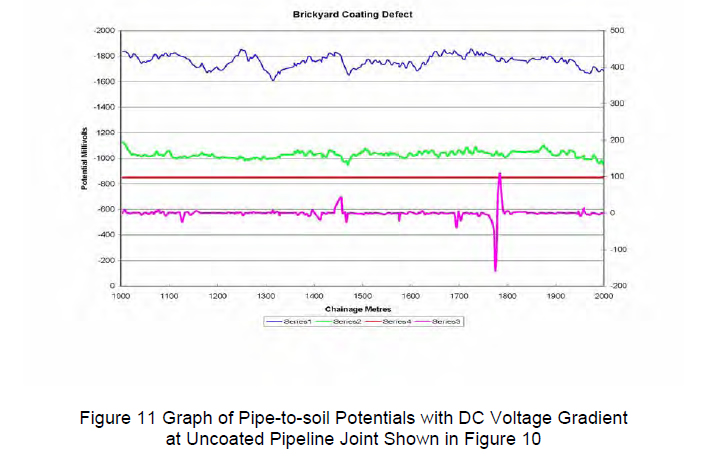
Figure 11 shows the rectifier on and off pipe-to-soil potentials along with the DC voltage gradients recorded at the coating defect. The uncoated pipe joint is located at the center of the sinusoidal waveform shown on the graph (Figure 11). The uncoated pipeline joint was located in an urban area subject to dynamic stray current from an electrified railway system. No evidence of corrosion was found and the exposed steel had a thick coating of calcareous material indicating the exposed pipe was cathodically protected.
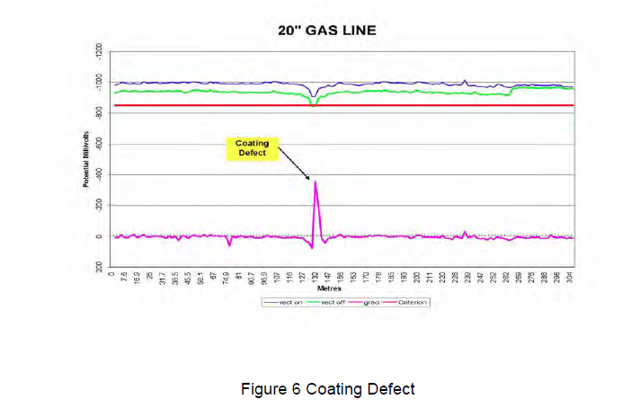
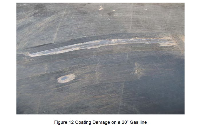
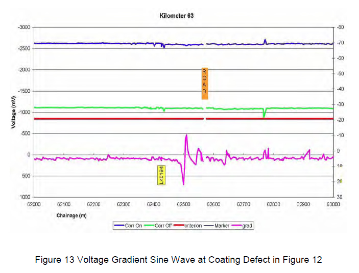
Figure 12 shows damage to the coating on a 20” gas line, probably caused by mechanical equipment. The coating defect was located during a combined CIPS and DCVG survey. Although there is little effect on the pipe-to-soil potential, the DC voltage gradient indicated that there was a coating defect. Figure 13 shows the results of the combined CIPS and DCVG survey which located the coating defect shown in Figure 12. There was no evidence of telluric or stray current activity at this location. The instant off pipe-to-soil potential averages –1100 millivolts with over 1500 millivolts of IR drop. After excavating for training purposes, the pipeline appeared clean with no evidence of corrosion. The instant off potential at this location was approximately -1000 millivolts.
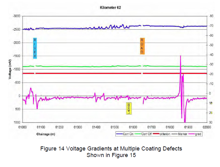
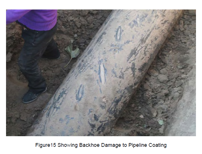
Figure 15 shows the coating defects located by the combined CIPS and DCVG survey shown in Figure 14, probably caused by a backhoe. It is evident that the pipeline was cathodically protected at the defect with no corrosion evident. This defect was excavated as part of a training exercise for pipeline personnel although the pipe-to-soil potentials indicated that the pipeline exhibited adequate levels of cathodic protection.
Stray and Telluric Interference
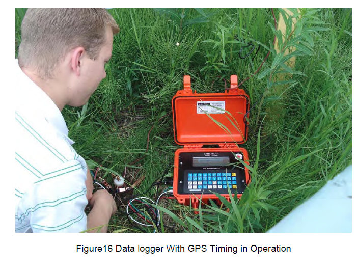
The combined CIPS and DCVG survey technique can be successfully applied in areas subject to stray and telluric current interference. Stray and telluric currents affect the rectifier on and instant off potentials recorded during a CIPS survey but not the DC voltage gradients. Thus, correction can be applied to the CIPS data (rectifier on and instant off potentials) using stationary logger data, which is stored using the same time base as the survey data. It is important that both the survey equipment and the stationary logger use the same programming and analogue to digital converter. For accurate CIPS data correction, the time of measurement of the rectifier on and instant off potentials in the survey data logger and the stationary data logger must coincide with great accuracy.
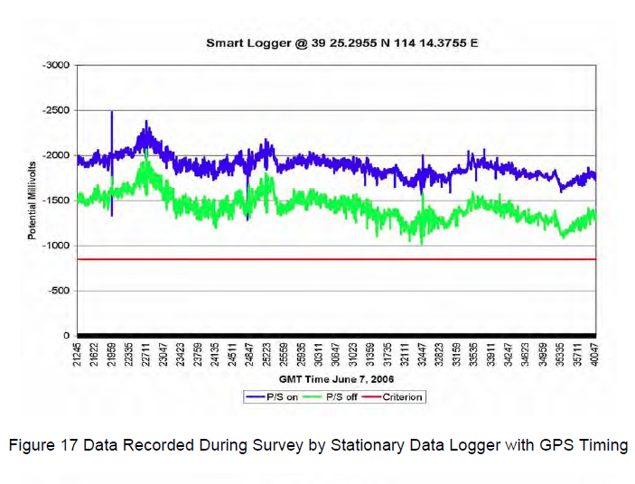
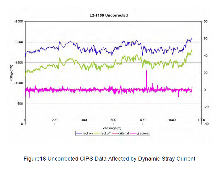
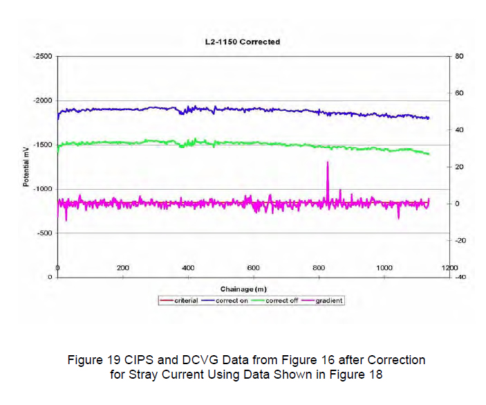
Figure 16 shows a stationary data-logger with GPS timing installed at a test station. Figure 17 shows a graph of the data recorded by a stationery logger with GPS timing. Fluctuation of the pipe-to-soil potential in excess of 400 millivolts is evident; this potential shift is due to dynamic stray currents from an electrified railway. The data recorded by the stationery data logger with GPS timing will be used to correct the CIPS data shown in Figure 18 recorded during a combined CIPS and DCVG survey. This correction of the CIPS data meets the requirement of recommended in the NACE International Standard Practice SPO0207-207. Figure 19 shows the CIPS and DCVG data before applying correction from the stationary data logger. The DCVG data was not corrected as it is unaffected by the DC stray current at this location. Where stray or telluric current interference is occurring it can be easily corrected using the stationary logger data and a spread sheet program. No special software is required.
Conclusions
In conclusion, combined CIPS and DCVG surveys can be performed on pipelines of any size;
there is no size restriction on this type of survey. It can be performed on large diameter crosscountry pipelines or on small diameter distribution piping. The combined CIPS-DCVG technique gives the corrosion engineer precise and accurate detailed information to allow for informed decisions on the operation of the cathodic protection system and the condition of the protective coating on the pipeline. The combined CIPS-DCVG technique requires an extra surveyor, but the survey can proceed at a walking speed saving both time and money and producing superior results.
The combined CIPS-DCVG survey can be successfully undertaken in areas subject to stray and/or telluric current interference. The CIPS potentials can be corrected by using a stationary data logger as described in NACE SP0207-2007.
Click to enlarge photos
References:
(1) World Pipelines September 2007 issue
(2) US Department of Transportation, Federal Highway Administration Publication, Corrosion Cost and Preventative Strategies in the United States Published 2002
(3)NACE International Recommended Practice RP0502-2002
(4)NACE International Standard Practice SP0169-2007
(5)NACE International Standard Practice SP0207-2007
Bibliography:
1. Peter Nicholson Corrosion 2007 Paper 07182
2. Peter Nicholson Corrosion 2007 Paper 07181
3. Peter Nicholson “External Corrosion Direct Assessment”, Pipeline Rehabilitation & Maintenance September 2006 Istanbul Turkey
4. Peter Nicholson “External Corrosion Direct Assessment”, Corcon 2004 New Delhi India
5. Peter Nicholson “Pipeline Integrity”, World Pipelines, March 2003
6. Peter Nicholson “Stray and Telluric Current Correction of Close Interval Potential Survey Data”, Eurocorr 2003 Budapest Hungary
7. R.L. Pawson: “Close Interval Potential Surveys – Planning, Execution, Results”, Materials Performance, February 1998, pp.16-21.
8. N.G. Thompson and K.M. Lawson, PRCI PR-186-807 Improved Pipe-to-Soil Potential Survey Methods, April, 1991.
9. NACE International Recommended Practice RP0502-2002
10. NACE International Standard Practice SP0169-2007
11. NACE International Standard Practice SP0207-2007
12. US Department of Transportation, Federal Highway Administration Publication, Corrosion Cost and Preventative Strategies in the United States Published 2002
13. World Pipelines, September 2007 issue
Peter Nicholson
Managing Director
Cathodic Technology Limited
15-1 Marconi Court, Bolton
Ontario, Canada L7E 1E2
Email: peter@corrosion-rust.com