
Elizabeth Nicholson, B.Eng.,Presented at: POLSKI KOMITET ELEKTROCHEMICZNEJ OCHRONY PRZED KOROZJĄ STOWARZYSZENIA ELEKTRYKÓW POLSKICH w WARSZAWIE September 19-21, 2012 in Jurata, Poland
Summary
Coatings prevent corrosion by creating a barrier between the structure and the electrolyte. Cathodic protection works by changing the potential of the structure to interfere with the corrosion process. Both work together to protect the structure. Surveys can be done to evaluate the condition of the coating and of the cathodic protection. By combining data from multiple types of surveys, anomalies can be prioritized for repair. Specialized digital recorders are capable of preforming cathodic protection and coating integrity surveys in one pass and storing that data with GPS co-ordinates for later analysis.
Corrosion has a global cost of billions of dollars every year. Corrosion of underground and underwater metallic structures such as pipelines and tanks can be managed. To protect underground metallic structures there are three main options; material selection, coating and cathodic protection.
Material selection begins in the design phase of a project. There is always a compromise between material, use and cost. There are corrosion resistant materials available for most situations but materials such as stainless steels are not often used due to expense and potential for corrosion underground.
 Corrosion occurs when an anode and cathode are connected with a metallic path and an electrolyte. A coating helps to prevent corrosion by removing the structure from contact with the electrolyte. Ideally, a coating is perfect and will never allow the structure to contact electrolyte. However, reality is that a very good coating still has defects. These defects can occur during initial application or installation of the structure, or they can also come from later damage by soil/rock shifting or other parties digging near the structure. Given a 1m diameter pipe, 100m long with a good coating that is 99.999% perfect, the 0.001% coating defect represents a 30 cm2 defect, or 30 separate 1 cm2 defects.
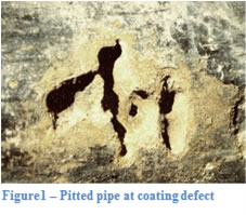
Corrosion is often accelerated at a coating defect as it exposes a small area of the structure to act as an anode for the rest of the structure. The defect concentrates the corrosion current in a small area. The pipe in Figure 1 had a coating defect which allowed corrosion pits to develop. This effect is of particular concern in AC hydro corridors as there is a direct relationship between corrosion rate and AC current density.
The other method used to prevent corrosion is to use cathodic protection to interfere with the electro-chemical process by making the structure more electronegative. Cathodic protection is applied through sacrificial anodes or impressed current from rectifiers. Voltage and current requirements are determined by a number of factors including the soil resistivity and coating properties. Larger areas of bare structure require more cathodic protection current.
By using both coatings and cathodic protection together, the ability to prevent corrosion is greatly improved. Coatings provide a physical barrier between the structure and the electrolyte, however coatings always have some defects. Cathodic protection changes the potential of the structure to prevent corrosion at the coating defects. A better coating results in less cathodic protection current being required, fewer anodes or less rectifier output is needed; both of which result in lower cost for the structure owner. Using the same 1m diameter pipe above with an estimated current requirement of 20 mA/m2, one can calculate the current required for protection. With a coating effectiveness of 99.9%, the current required would be 6 mA. With a coating effectiveness of 99.999%, the current required would be 0.06 mA. Over a long stretch of pipeline and over time the energy savings can be significant with a better quality of coating. During design of the pipeline or other structure, the design engineer must take into account the cost of various coatings, the cost of cathodic protection and the ongoing maintenance costs of both. Current practice is to install the best coating possible and install a cathodic protection system that can be adjusted as needed.
Over time both coating integrity and cathodic protection levels can change. Construction in the area of the structure can damage the coating and change the soil resistivity. Seasonal changes can change the level of moisture is the soil, affecting the soil resistivity. Monitoring the coating integrity and the cathodic protection level is important to maintain the integrity of the structure.
 There are a number of possible above ground coating integrity surveys. All involve generating a signal on the pipeline and surveying the line for voltage gradients. DCVG creates a DC pulse, often by interrupting the source of cathodic protection, and then walking the line with two electrodes looking for a voltage gradient in the soil. ACVG inputs an AC pulse in the soil; the surveyor also walks the line measuring AC voltage gradients. A Pearson survey is also similar to ACVG; using a higher frequency AC signal and registering the voltage gradient as an audible signal.
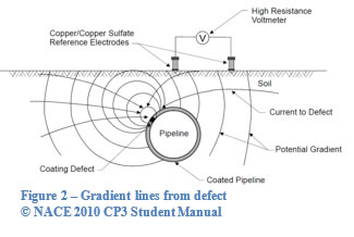
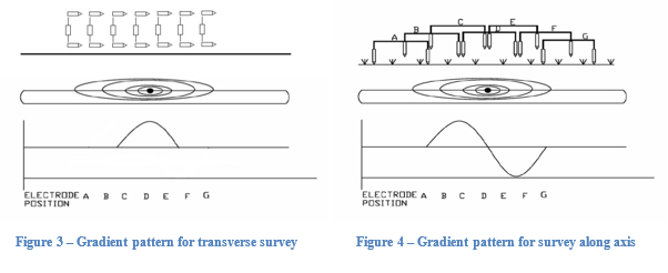
Defects in the coating generate an electrical signal in the form of concentric potential gradients emanating from the defect. The survey involves a surveyor walking along the line with two electrodes. When the electrodes are across the concentric voltage gradient lines a voltage is read between the two electrodes, as shown in Figure 2. The closer one electrode is to the centre of the defect, the larger the voltage reading. The electrodes can be transverse to the pipe as shown in Figure 3 or along the axis as shown in Figure 4. A transverse survey produces a spike where the defect exists as the two electrodes are capturing the potential across the most gradient lines. A survey along the axis produces a spike prior to the defect as one electrode is near the defect and the second is able to capture the most gradient lines. The potential reading then crosses zero as the two electrodes are ‘balanced’ at the centre of the defect. Finally, as the surveyor moves away, a valley is shown after the defect as the electrodes are now reversed.
A knowledgeable surveyor can approximate the shape of the defect by observing the shape of the gradient found. With DCVG, the size of the defect can be approximated based on the magnitude of the gradient compared to the DC signal strength (%IR). The signal from the defect has a limited strength. This is partially dependant on the signal generated, depth of pipe and soil conditions. It is possible for small defects to be missed in voltage gradient surveys. It is possible to calculate the effect of a theoretical equivalent hemisphere. According to Ohm’s law, V=IR, there is a direct relationship between potential and resistance.
Elizabeth Nicholson, B.Eng. Manager of Cathodic Technology Ltd
Presented at:
POLSKI KOMITET ELEKTROCHEMICZNEJ OCHRONY PRZED KOROZJĄ STOWARZYSZENIA ELEKTRYKÓW POLSKICH w WARSZAWIE
September 19-21, 2012 in Jurata, Poland